

Views: 0 Author: Site Editor Publish Time: 2026-10-26 Origin: Site


Upgrading your dashboard with a performance gauge setup is an exciting engineering project. However, when you are crawling under the dash with a pair of wire strippers, taking electrical shortcuts can quickly lead to disaster. Far too often, DIY mechanics attempt to piggyback an external warning light directly onto the main engine speed signal wire. While this might seem like a harmless time-saver, it is a critical mistake that can fry a costly Engine Control Unit or corrupt your ignition timing. In this comprehensive guide, we will explore the underlying electrical science that makes a separate circuit an absolute necessity. Whether you are installing a high-revving racing tachometer featuring an 80mm display and 7-color illumination, or a standard street analog gauge, isolating your power delivery is essential.
Signal Protection: Tapping a shift light directly into a data signal wire degrades the signal pulse, often causing inaccurate readings or bouncing gauge needles.
Current Draw Management: High-intensity lights draw significantly more electrical current than a standard signal circuit can safely handle, which risks damaging sensitive ignition components.
Precise Triggering: A separate circuit utilizes a programmable module or an RPM pill to trigger the light at an exact moment, functioning completely independently of the gauge mechanical sweep.
Safer Upgrades: Implementing a dedicated 12-volt relay ensures that your performance instrumentation operates cleanly without interfering with the factory wiring harness of the vehicle.
To fully grasp why a separate circuit is an engineering requirement rather than a mere suggestion, it is necessary to examine the fundamental functions of both components. While they operate in tandem to provide engine speed data to the driver, their electrical characteristics are entirely different.
A standard gauge is a precision instrument designed to measure the rotational speed of an engine, displayed in Revolutions Per Minute. To calculate this speed, the unit relies on electrical pulses generated by the ignition coil, distributor, or Engine Control Unit. Every time a spark plug fires, or a sensor detects a rotation, a microscopic pulse is sent through the signal wire.
This signal is typically a low-voltage square wave. It is a communication line designed exclusively for transmitting data. The internal circuitry reads the frequency of these pulses and translates that data into the smooth needle movement on your dashboard. Because it is strictly a data line, it operates on mere milliamps of current and is absolutely not designed to provide physical power to external accessories.
In contrast, a shift light serves a completely different electrical purpose. It is a high-intensity visual indicator programmed to illuminate instantly when the engine reaches a pre-determined speed threshold. Its primary function is to alert the driver to grab the next gear without requiring them to take their eyes off the track to read a moving needle.
Unlike a sweeping needle that moves continuously based on data interpretation, a warning light requires a sudden and substantial burst of electrical power. It acts as a heavy-duty switch. When the target threshold is hit, the module must draw enough amperage to instantly illuminate a blinding incandescent bulb or a high-output LED array. This sudden, violent demand for power is exactly where the conflict between the two devices originates.
The most immediate and noticeable issue that arises from improper wiring is signal degradation. Specifically, when electrical systems share a single wire intended for data, introducing a load-bearing device compromises the integrity of that entire network.
A common error during weekend garage installations is splicing the power wire of the external light directly into the main signal wire. In electrical terms, this creates an unregulated parallel circuit. When the light activates at the redline, it attempts to pull the heavy power it needs to illuminate directly from the delicate signal line.
Because the engine computer or ignition coil is only outputting a low-amperage data pulse, the sudden draw from the light causes a severe voltage drop across the circuit. Consequently, the square wave signal loses its amplitude, and electrical noise is introduced into the line. The clean and sharp pulses that the gauge relies on become distorted, weak, and unreadable.
This massive voltage drop leads directly to the dreaded bouncing needle effect, which is a frequent troubleshooting nightmare found across automotive forums. When the light tries to pull power from the signal wire, the voltage of the data pulse drops below the minimum threshold required by the internal microprocessors of the gauge.
As a result, the gauge temporarily loses the signal altogether. The needle will instantly drop to zero, bounce erratically, or freeze in place. Once the driver shifts, the engine speed drops, the light turns off, and the signal voltage miraculously recovers. This erratic behavior renders the gauge completely useless precisely when you need it most, right at the absolute upper limits of your engine power band.
Modern vehicles and high-performance aftermarket ignition systems utilize highly sensitive microprocessors. These advanced systems expect a specific and consistent resistance along with a minimal current draw on their output pins.
When a high-draw accessory is spliced into this line, it forces the ignition module to output more current than its internal drivers were designed to handle. Over time, this excessive thermal load can burn out the internal pathways of the computer, leading to catastrophic engine management failure. A separate circuit isolates the high-current draw, keeping the data stream pure and protecting your expensive electronics.
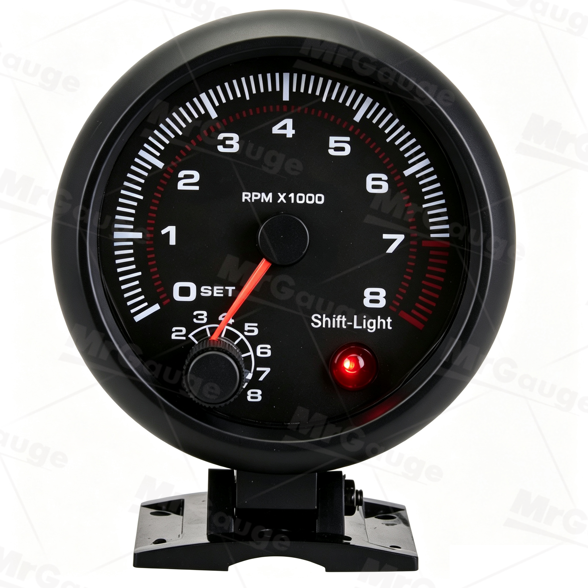
Understanding the fundamental difference between data transmission and power consumption is critical when modifying automotive electrical systems. The necessity of a separate circuit ultimately boils down to safe current management.
Looking at recent trends in the automotive aftermarket, there is a massive shift toward Controller Area Network bus integration and solid-state power distribution modules. Modern vehicles rely heavily on complex, multiplexed digital networks rather than traditional analog wiring. Despite this digital revolution, the fundamental physics of current draw remain unchanged. When retrofitting high-draw accessories into both vintage builds and modern data-equipped vehicles, electrical isolation is more critical than ever. Failing to separate high-current lighting from delicate data networks can trigger cascading error codes and permanently damage sensitive digital-to-analog converters.
Electrical current is measured in amperes. As established, a signal circuit operates on a microscopic scale, often between 20 and 50 milliamps. The wiring harness, the gauge internals, and the output drivers are all strictly engineered for this tiny load.
Furthermore, an external warning light requires significant power to achieve its track-ready brightness. Even highly efficient modern LED arrays can draw several hundred milliamps, while traditional halogen styles can pull anywhere from 1 to 5 amps. Attempting to pull 5 amps through a circuit designed for 50 milliamps is the electrical equivalent of trying to force a fire hose volume of water through a garden hose. The resulting heat and resistance will inevitably melt wires, blow fuses, and destroy circuit boards.
To safely manage this high current draw, building a separate circuit utilizing a standard 12-volt automotive relay is mandatory. Think of a relay as an electromagnetic bridge that allows a highly sensitive, low-current signal to safely control a high-current device.
In a properly wired setup, the trigger module sends a tiny and perfectly safe signal to the relay coil. This tiny signal magnetizes the coil, pulling an internal heavy-duty switch closed. Once closed, the relay pulls the heavy-lifting high-amperage current directly from the vehicle battery through a dedicated inline fuse and sends it straight to the light. The engine computer and the gauge never experience the electrical burden of the illumination, ensuring complete system safety.
Beyond basic electrical safety, a separate circuit is required for functional accuracy. A warning light must turn on at an exact and programmable moment, which requires dedicated logic hardware rather than a simple power wire.
A standard gauge is primarily a display device. It reads the incoming signal and physically moves a needle across a dial. Unless it is specifically manufactured with internal switching logic, a standard unit does not have a mechanism to output power at a specific numerical value.
Therefore, you cannot simply wire a bulb to the back of a standard gauge and expect it to magically know when to turn on. The light requires an independent logic board to monitor the pulse frequency and physically close the circuit when the target redline is reached.
This independent logic comes in the form of an activation switch. Historically, old-school racers used analog pills, which are small plug-in modules containing precise resistor networks. If you wanted the flash to happen at 6,000 revolutions per minute, you physically plugged in a specific 6,000 resistor pill.
Today, digital window switches and programmable micro-controllers are much more common. These modern devices read the signal, but they require their own dedicated 12-volt power and ground circuits to operate their internal processors. They monitor the signal passively, and when the target is hit, they send a trigger voltage to the relay. This independent processing ensures pinpoint accuracy, completely unaffected by the mechanical latency of a sweeping gauge needle.
Different vehicle applications require vastly different instrumentation. The type of engine bay you are working in dictates exactly how a separate circuit should be integrated. The principles of electrical isolation remain constant, but the practical execution varies based on your equipment.
In competitive motorsports, drivers experience extreme vibration, high G-forces, and rapid engine acceleration. They rarely have time to look down at a dial. Therefore, track drivers often rely on massive and ultra-bright external lights mounted directly in their line of sight. Because these external units are so powerful, their current draw is substantial. Wiring a heavy-duty separate circuit with a high-capacity 40-amp relay is absolutely critical to prevent ignition failure during a high-speed pass.
Diesel engines present a highly unique electrical challenge. Because traditional diesels do not use spark plugs or an ignition coil, there is no conventional ignition pulse to read. Instead, a diesel engine tachometer—such as an 85mm unit designed for 0 to 4000 RPM ranges on 12-volt or 24-volt systems—typically receives its engine speed data from the alternator alternating current tap, known as the W terminal, or from a magnetic proximity sensor reading the flywheel teeth.
These signals operate at entirely different frequencies and much lower voltages than gasoline systems. If you are adding a warning light to a diesel rig, you absolutely cannot use a standard gasoline activation switch. You must source a specialized diesel-specific module designed to interpret alternator frequencies, and use that module to trigger your separate relay circuit safely.
Many enthusiasts upgrade their factory dashboards to a sleek white LED tach specifically calibrated for 4-cylinder engines to improve nighttime visibility and achieve a cleaner, modern aesthetic. While LED backlighting technology is highly efficient and draws less baseline power than older incandescent bulbs, the fundamental rules of electrical isolation still apply. If you intend to add a standalone shift light to a modern LED setup, you must still utilize a separate circuit to prevent the delicate LED drivers inside the gauge from being subjected to voltage drops.
When planning an instrumentation upgrade, consumers must decide between purchasing a unit with an integrated lighting system or building a modular circuit for an external light. Both approaches have distinct engineering merits depending on your mechanical comfort level and dashboard layout.
For many users, the most reliable and straightforward solution is to purchase an integrated shift light tachometer that features adjustable warning thresholds built directly into the performance gauge. In these premium units, the manufacturer has already done the hard work. They have engineered the internal printed circuit board to safely handle both the data processing and the high-current power distribution.
The internal logic board monitors the data and switches power to the built-in LEDs using robust solid-state transistors. Because this is engineered as a single and closed system, there is virtually no risk of current overload or signal degradation. This completely eliminates the need for the end-user to wire external relays or hunt down compatible activation switches.
If an enthusiast prefers the vintage aesthetic of their current dashboard but requires a visual shift cue, an external setup is the only viable option. This method requires purchasing a standalone activation switch, a 12-volt relay kit, and the physical light itself.
While this requires more complex wire routing, precise crimping, and a stronger understanding of automotive electrical systems, it offers superior customization. The driver can choose the exact size, color, and mounting location of the light. This is a feature highly preferred in dedicated track cars where peripheral visibility is paramount.
| Feature | Integrated Shift Light Gauge | External Shift Light Setup |
|---|---|---|
| Installation Complexity | Low. Features simple plug-and-play wiring. | High. Requires relays, switches, and custom routing. |
| Signal Protection | Engineered internally by the factory. | Requires strict separate circuit isolation. |
| Customization | Limited to the factory design. | High. Choice of light size, color, and placement. |
| Ideal Application | Street cars, mild tuning, and clean interiors. | Dedicated race cars and custom track builds. |
If you have chosen the path of installing an external unit, adhering to strict electrical best practices is non-negotiable. Proper installation is the only way to guarantee accurate readings and protect your vehicle from electrical fires.
Attempting to wire a high-current circuit with substandard materials will inevitably lead to overheating. Before beginning the installation, ensure you have the correct components on your workbench:
A standard 4-pin or 5-pin 12-volt automotive relay. A 30-amp or 40-amp capacity is typically sufficient.
An inline fuse holder and appropriate fuses, usually 5 to 10 amps, placed near the battery.
Automotive-grade primary wire, utilizing 18-AWG for delicate signals and 14-AWG for heavy power lines.
Quality wire strippers, crimpers, ring terminals, and adhesive-lined heat-shrink tubing to prevent corrosion.
A standalone activation switch compatible with your specific ignition type.
To correctly isolate the system, the wiring must be routed logically to separate the data signal from the heavy power load. Here is the standardized engineering logic for wiring your relay:
Power Delivery on Pin 30: Run a dedicated power wire directly from the vehicle battery. This wire must go through an inline fuse before connecting to Pin 30 on the relay. This ensures the light draws its heavy current safely from the source.
Grounding on Pin 85: Establish a solid and paint-free chassis ground for the relay. Poor grounds are the leading cause of flickering lights and delayed activation.
Signal Isolation: Tap the vehicle main data signal wire. This wire should only connect to the gauge itself and the input wire of your activation switch.
Triggering the Relay on Pin 86: Connect the output trigger wire of the activation switch to Pin 86. When the target threshold is reached, the switch sends a tiny, safe low-amp signal to magnetize the relay coil.
Powering the Light on Pin 87: Connect Pin 87 to the positive wire of the external light. When the relay snaps closed, battery power flows smoothly from Pin 30 to Pin 87, illuminating the light instantly without corrupting the delicate data signal.
Wiring a separate circuit is absolutely essential for safety, as it completely protects your vehicle electrical system from devastating voltage drops and thermal overloads. Furthermore, a dedicated circuit prevents erratic, bouncing gauge readings and keeps your expensive ignition components safe from premature failure. Whether you are monitoring a heavy-duty industrial diesel setup or pushing a custom track car to the redline, electrical isolation matters. Always separate the heavy power delivery from the delicate data signal to ensure pinpoint accuracy for your shifts. If you are ready to upgrade your dashboard with professional-grade instrumentation, browse our selection of quality gauges and accessories at MrGauge today, and ensure your project is done right the first time.
No. Wiring a high-current accessory directly to the negative terminal of the ignition coil is highly detrimental. The ignition coil requires a specific, uninterrupted voltage threshold to saturate and fire the spark plugs. A light will drain this necessary voltage, leading to a weak spark, engine misfires under heavy load, and potential back-feeding that can permanently damage the internal diodes of the light. You must use an activation switch and an isolated relay.
This is the classic and empirical symptom of not having a separate circuit installed. The gauge relies on a consistent, low-voltage electrical pulse to calculate engine speed. When the light activates, it draws significantly more current than the signal wire can provide. This effectively steals the electrical pulse, causing the signal voltage to drop below the readable threshold of the gauge. The needle drops to zero because the gauge briefly believes the engine has stopped turning altogether.
Yes. Because diesel engines lack a traditional ignition coil, they do not produce the standard ignition pulses found in gasoline engines. A diesel setup usually receives its data from the alternator alternating current frequency or a magnetic flywheel sensor. Standard activation switches cannot read these unique signals. You will need a diesel-specific switch designed to interpret low-frequency signals to trigger your separate relay circuit accurately.
For the low-current signal wires and the relay trigger, a standard 18-AWG automotive wire is perfect. However, for the high-current power delivery wires connecting the battery to the relay and the relay to the light itself, you should step up to a thicker 14-AWG wire. This thicker gauge prevents resistance buildup and ensures the light receives full voltage for maximum brightness.
Absolutely. If a high-draw accessory is incorrectly spliced into the ignition coil negative terminal or the main communication wire of the engine computer, it creates parasitic draw. This steals the electrical energy required to properly charge the ignition coils. At higher engine speeds, this voltage drop prevents the spark plugs from firing powerfully enough to ignite the fuel mixture, resulting in a noticeable high-speed misfire.
It depends entirely on your specific application and environmental needs. An integrated gauge is objectively easier to wire because the internal circuitry is already separated, optimized, and protected by the manufacturer, reducing potential points of failure. However, professional drag racers often prefer a massive external light mounted at eye level on the roll cage for maximum peripheral visibility, which necessitates the creation of a separate, high-current circuit.
A standard 12-volt, 30-amp or 40-amp automotive relay is more than sufficient for almost any external warning light on the market, including high-intensity modern LED setups. While most LED arrays draw less than 5 amps, using a 30-amp relay provides a massive safety overhead. This prevents the internal contacts of the relay from overheating or fusing together during rapid, repeated gear shifts, ensuring long-term reliability in high-vibration environments.


