

Views: 0 Author: Site Editor Publish Time: 2026-10-31 Origin: Site


Is your engine actually boiling over, or is the dashboard simply reporting false data? False overheat warnings cause unnecessary panic. They also frequently lead to misguided and expensive part swaps. Before you drain the coolant or replace a perfectly good thermostat, field engineers rely on a foolproof bench procedure. This method isolates the sensor for precise calibration. It completely bypasses the vehicle's aging wiring harness and potential grounding faults.
In this comprehensive engineering guide, we detail the exact procedures for bench-testing your thermal instruments. By executing both hot and cold fluid tests, you will definitively prove whether your dial is highly accurate or ready for the scrap bin.
The Fluid Immersion Standard: Suspending your sensor in heated water alongside a calibrated reference thermometer remains the most objective way to verify thermal accuracy outside the engine block.
System Differences: Testing a mechanical unit requires submerging the physical capillary bulb to measure fluid expansion. Conversely, an electrical sender requires measuring electrical resistance in Ohms using a digital multimeter.
Baseline Calibration: Utilizing a properly prepared ice bath at 32 degrees Fahrenheit and a boiling water setup at 212 degrees Fahrenheit provides two scientifically stable reference points.
Systemic Decay: Classic automotive architectures often suffer from electrical degradation. Degraded wiring or faulty instrument voltage regulators frequently cause erratic dashboard readings.
The automotive restoration and heavy-duty equipment sectors are experiencing a major diagnostic shift. Mechanics no longer replace cooling components based solely on dashboard readings. The increasing scarcity of reliable original equipment sensors and the rise of complex engine builds demand rigorous component-level verification.
Industry data suggests over half of suspected cooling system failures actually stem from electrical faults rather than mechanical overheating. Consequently, bench-testing has evolved from an optional check into a mandatory standard operating procedure. This diagnostic rigor prevents the disposal of functional vintage dials. Furthermore, it ensures modern aftermarket replacements perform to exact thermal specifications right out of the box.
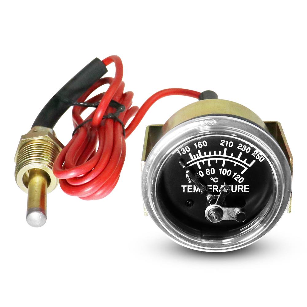
In automotive diagnostics, testing a temperature gauge against a bath involves creating a controlled scientific environment. Rather than guessing the coolant temperature inside the engine water jacket, you utilize a heated container to establish an easily measurable thermal baseline.
Leaving the sensor threaded inside the engine block introduces too many uncontrollable variables. Fluctuating coolant flow rates, localized air pockets in the intake manifold, and inconsistent engine block grounding will skew your data. By unthreading the sensor and placing it in a separate body of water, you completely isolate the component from the vehicle's ecosystem.
The primary goal is objective verification. By comparing the reading displayed on your dashboard dial against a verified laboratory thermometer, you determine if the instrument is reading accurately, drifting out of specification, or failing entirely.
Executing this calibration safely requires specific tools. Relying on improvised equipment leads to inaccurate baseline readings and potential safety hazards.
You will need a deep metal pot large enough to fully submerge the sensor without it physically touching the bottom. A portable electric hot plate serves as the ideal heat source for workbench use. Crushed ice and cold water are absolutely necessary for establishing the freezing point baseline.
Precision relies entirely on your control instruments. A highly accurate digital cooking thermometer provides the baseline reading. A digital multimeter is essential for measuring the resistance of electrical senders. Finally, insulated alligator clips prevent short circuits and keep your hands safely away from the heat source.
Understanding the fundamental differences between instrument types is crucial before beginning any bench test. Below is a breakdown of how these two distinct technologies operate and fail.
| Feature | Mechanical System | Electrical System |
|---|---|---|
| Operating Principle | Fluid/gas expansion through a sealed capillary tube. | Thermistor alters electrical resistance based on heat. |
| Testing Metric | Visual dial sweep versus control thermometer. | Ohms resistance measured via digital multimeter. |
| Common Failure Mode | Kinked tube leaking expansion gas. | Internal short circuit or poor block grounding. |
| Typical Display Range | 100 to 250 degrees Fahrenheit. | Varies heavily by OEM specification. |
Mechanical systems operate entirely independently of the vehicle's electrical harness. They rely on a sealed capillary tube filled with a temperature-sensitive fluid. As the fluid heats up, it expands and travels up the tube to physically push the needle across the dial.
When extracting a mechanical water temp gauge, you must handle the assembly with extreme care. The sensor bulb, the capillary line, and the dashboard head constitute a single, permanently sealed unit. Carefully unthread the mounting nut at the engine block. You must ensure you do not bend or crimp the line. Even a minor kink restricts internal fluid expansion and permanently destroys the instrument.
Fill your pot with water and activate the heat source. Suspend the brass sensing bulb directly in the water column alongside your control thermometer. Do not allow the bulb to rest against the bottom of the metal pot. The metal conducts heat directly from the burner, which means it reads significantly hotter than the water itself and invalidates your data.
As the temperature rises, monitor both displays. Around 150 degrees Fahrenheit, the needle should lift off the cold peg. As the water reaches 180 to 190 degrees Fahrenheit, you enter the normal operating range for standard engines. Finally, bring the water to a rolling boil. If the needle matches the control thermometer within a five-degree variance, the unit functions perfectly. Conversely, if the needle sticks, the internal Bourdon tube suffers from metal fatigue.
Electrical systems operate on entirely different engineering principles. The sender unit threaded into the engine block is typically a Negative Temperature Coefficient thermistor. As the coolant gets hotter, the internal electrical resistance decreases. This drop in resistance allows more current to flow to the dashboard dial.
To test an electrical sender, you only need your digital multimeter initially. Set the multimeter to the Ohms setting. Connect one probe to the top terminal of the sender. Clip the other probe to the brass threaded body, which acts as the ground.
Using insulated clips, lower the tip of the sender into the hot water. Ensure the top electrical terminal remains completely dry to prevent shorting the reading. Record the resistance at specific intervals, such as 150 and 200 degrees Fahrenheit. You must cross-reference these recorded values with the manufacturer resistance chart. If your readings severely deviate from published specifications, the sender is internally defective.
While boiling water tests the upper thermal limits, establishing a cold baseline is equally critical. Industry standards dictate that a properly constructed ice bath is the most reliable way to create a guaranteed 32-degree Fahrenheit environment without specialized laboratory equipment.
Fill an insulated container entirely to the brim with crushed ice to minimize warm air gaps. Pour cold water into the container just until it reaches the top of the ice. Stir the mixture vigorously and let it sit for a few minutes to allow thermal equalization.
Submerge the sensor into the ice bath. Agitate it slightly to prevent a localized micro-climate of warmer water from forming around the bulb. If you run a modern digital water temperature meter, checking its lowest threshold confirms the internal calibration remains linearly accurate. For electrical units, establishing this cold baseline resistance proves the thermistor has not shorted out entirely.
If your bench test reveals the sensor is perfectly accurate but the dashboard still displays erratic readings, you must investigate systemic factors. The instrument is only as reliable as its installation environment.
Poor engine block grounding represents the leading cause of artificially high readings in electrical setups. Mechanics often mistakenly wrap the sender threads heavily in thick Teflon tape to prevent coolant leaks. This insulation completely blocks the electrical ground. You should apply a liquid conductive thread sealer or leave the bottom two threads bare.
Furthermore, many vehicles utilize an Instrument Voltage Regulator behind the dashboard. This component steps down the vehicle power to a constant five volts for delicate instruments. If this regulator fails and supplies a full twelve volts, the dial will peg to maximum hot immediately upon startup.
Restoring classic 4x4s presents unique diagnostic hurdles due to aging electrical architectures. A factory Jeep CJ water temp gauge often suffers from cluster anomalies mimicking catastrophic engine failure.
Vintage utility vehicles frequently utilize a pulsing voltage system. A small bimetallic strip inside the cluster rapidly pulses power on and off to create an average output. As this strap ages, the contacts can weld closed. This failure sends constant high voltage through the system, driving the needle into the red zone even when the engine block is ice cold.
When testing classic senders, look for specific resistance ranges unique to that era. A functional vintage sender might measure around 73 Ohms at room temperature and drop to 13 Ohms in boiling water. If your bench test confirms these numbers, direct your repairs toward the dashboard grounding strap. Upgrading to a versatile mechanical unit with 12-volt to 24-volt illumination compatibility often bypasses these legacy electrical headaches entirely.
After conducting both thermal tests, you possess definitive data to make a logical engineering decision. If your setup passes the bath test perfectly, the issue lies elsewhere in the vehicle. You likely have a stuck thermostat or a failing water pump.
However, if the component fails on the bench, replacement is mandatory. Use these parameters to guide your selection:
If your vehicle suffers from chronic electrical grounding issues, switch to a 52mm universal mechanical gauge. Look for standard display ranges spanning 100 to 250 degrees Fahrenheit, or 38 to 121 degrees Celsius. This pure physical tracking eliminates wiring faults.
If you prefer modern precision and your wiring is intact, upgrade to a quick-response electrical unit compatible with heavy-duty engine profiles. For dashboard consolidations, a two-in-one LCD electronic instrument tracking both coolant heat and battery voltage maximizes monitoring efficiency in tight cabin spaces.
Yes, but the results remain highly subjective. You can use an infrared thermometer to scan the surface of the thermostat housing while the engine runs. By comparing the infrared surface reading to your dashboard dial, you get a rough estimate. However, external surface temperatures are often ten to fifteen degrees cooler than the internal coolant flowing past the sensor.
For most standard internal combustion engines, normal operating temperatures range between 190 and 210 degrees Fahrenheit. This depends heavily on the temperature rating of the installed thermostat. Your needle should sit comfortably in the middle of its sweep. If it consistently creeps above 220 degrees Fahrenheit, inspect the cooling system immediately.
No. Residential water heaters are legally regulated to prevent scalding. Tap water usually maxes out around 120 degrees Fahrenheit. This temperature is far too low to test the critical upper limits of an automotive sensor. You must use a controlled pot of boiling water.
A dial that suddenly pegs to maximum hot immediately upon turning the key indicates a severe electrical fault. This is almost always caused by a dead short to the ground in the sender wire. It can also result from a catastrophic failure of the instrument voltage regulator supplying excessive power to the dial.
A healthy sensor should begin reacting almost immediately upon immersion. For mechanical units, you will see smooth needle movement within five to ten seconds as the internal fluid expands. Electrical thermistors change resistance instantly, which your multimeter will register in real-time as the probe heats up.
While exact specifications vary by manufacturer, a standard automotive electrical sender typically reads between 2,000 and 3,000 Ohms at an ambient room temperature of 68 degrees Fahrenheit. As the sensor enters boiling water, this resistance sharply drops into the 100 to 200 Ohm range.
Guessing coolant parameters based on faulty dashboard data invites catastrophic engine damage. By applying the rigorous water bath testing methods outlined above, you take control of your vehicle's thermal diagnostics. If your current equipment fails the bench test, do not risk your engine block. Upgrade to highly calibrated, industrial-grade monitoring solutions. Explore the complete lineup of precision mechanical and electronic instruments at MRGAUGE to secure absolute accuracy for your next build.


