

Views: 0 Author: Site Editor Publish Time: 2026-10-30 Origin: Site


Picture this familiar scenario in the shop or your home garage. You just spent an entire weekend meticulously installing a brand-new 52mm dashboard upgrade. You turn the ignition key. You expect to see precise engine vitals. Instead, the gauge needles bounce erratically or display wildly inaccurate numbers. It is a frustrating moment that often leads to hours of chasing wires under the dash.
Empirical data from automotive electrical diagnostics reveals a stark reality. Nearly 90 percent of aftermarket instrument malfunctions stem from a single overlooked issue: poor grounding. Relying on flimsy chassis grounds or messy daisy-chain wiring methods creates severe electrical bottlenecks.
The definitive solution to this problem is implementing a shared ground bus. Centralizing the ground connection establishes a zero-resistance pathway. This is the ultimate secret to stable, accurate, and reliable readings. Whether you are installing a high-performance 3-in-1 setup, a highly sensitive temperature monitor, or a mechanical-to-electrical pressure tracker, utilizing a shared ground bus is a non-negotiable step for a professional-grade installation.
Eliminates Ground Loops: A shared ground bus prevents voltage drops and electrical noise that cause erratic, bouncing needle behavior.
Ensures Pinpoint Accuracy: Centralized grounding guarantees that highly sensitive instruments read actual engine conditions rather than electrical interference.
Simplifies Troubleshooting: Implementing a hub-and-spoke wiring method makes it incredibly easy to isolate and fix electrical issues compared to convoluted daisy-chaining.
Protects Your Investment: Proper zero-resistance wiring extends the lifespan of your dashboard instruments and prevents dangerous electrical shorts behind the dash.
To fully grasp why a centralized ground is mandatory, you must first establish a foundational knowledge of what makes up these kits. These specific instruments demand precise electrical foundations for a reason.
A standard 52mm three-meter cluster typically consists of a voltmeter, a water temperature monitor, and an oil pressure monitor. Each of these devices operates on fundamental principles of electrical resistance. For instance, the pressure sender unit mounted to the engine block contains a diaphragm and a variable resistor. As engine pressure increases—often ranging from 0 to 100 PSI—the internal resistance changes. This sends a specific voltage signal back to the dial.
Similarly, a universal temperature gauge utilizes a thermistor. This highly specialized component translates physical heat into electrical resistance, accurately tracking ranges from 100 to 250 degrees Fahrenheit. Because these instruments measure minute changes in ohms, they are incredibly sensitive to any unintended voltage drops caused by poor grounding techniques.
A common misconception in automotive wiring is treating all ground wires equally. Modern clusters feature two distinct electrical circuits. One is dedicated to the sensor signal, and another powers the backlight illumination. The signal senders require an absolutely clean ground reference to measure engine vitals accurately. In contrast, modern LED backlights draw a continuous, relatively high current that can inadvertently introduce electrical noise into the circuit.
If the illumination ground and the sensor ground share a poor connection to the chassis, the current from the LED lights can back-feed. Grounding both the illumination and the sensors to a centralized bus bar ensures that the power draw from the lights does not interfere with the delicate resistance readings transmitted by the engine sensors.
Transitioning from amateur DIY wiring to professional-grade techniques requires a fundamental shift in how electrical routing is handled. A shared ground bus is a simple yet highly effective component that centralizes your electrical pathways into one organized location.
In professional electrical engineering, this centralized method is known as a hub-and-spoke model. Imagine a bicycle wheel where the ground bus—a solid block of highly conductive brass or copper—acts as the central hub. Each individual instrument in your cluster has its own dedicated wire acting as a spoke, running directly to this hub. Consequently, this setup prevents the instruments from sharing the same physical wire along their route, thereby completely isolating their electrical loads.
Many novice installers simply crimp a ring terminal to their wires and drive a self-tapping screw into the nearest metal bracket under the dashboard. This is a critical error. The vehicle cabin is not a reliable ground path for precision instruments. Layers of primer, paint, surface rust, structural adhesives, and seam sealers create immense electrical resistance. Furthermore, dissimilar metals—such as a copper wire bolted to a steel frame—can induce galvanic corrosion over time. When a ground connection possesses inherent resistance, it ceases to be a true zero reference point.
Looking at broader automotive industry trends, the aftermarket is currently experiencing a massive surge in restomods and complex EV conversions. Today's custom builds are packed with high-draw electronics. Builders are integrating aftermarket EFI systems, massive electric cooling fans, and high-output infotainment setups. This evolution makes traditional chassis grounding entirely obsolete. The ambient electrical noise in a modern build is exponentially higher than it was decades ago. To combat this, industry professionals are universally adopting centralized power distribution and grounding architectures. This ensures sensitive digital and analog instruments remain perfectly accurate amid intense electrical interference.
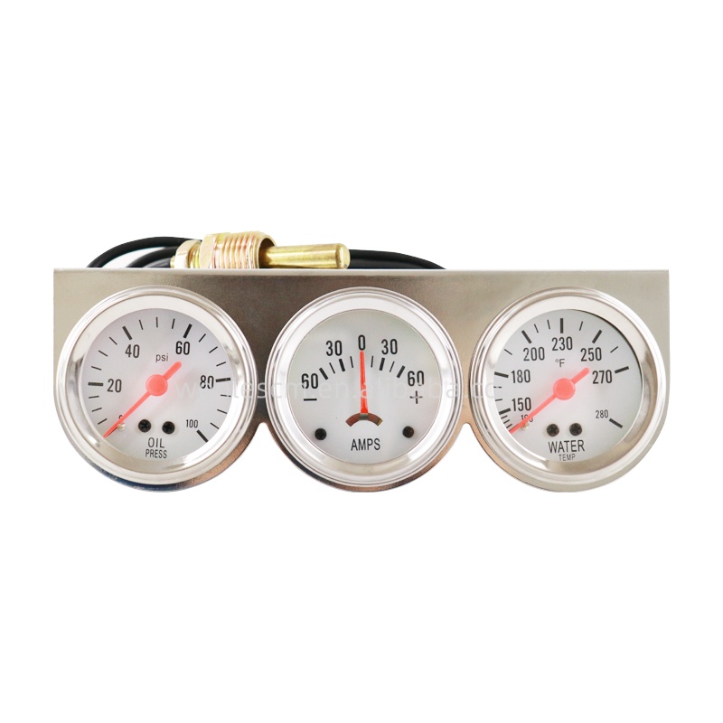
Providing a rock-solid electrical foundation is not merely about making the wiring look aesthetically pleasing. It is a strict technical requirement for accurate vehicle monitoring. Here is the objective reasoning behind utilizing a central bus bar.
A ground loop occurs when multiple devices are grounded at different physical locations that have slightly different voltage potentials. Grounding one meter to the steering column and another to the firewall might result in a 0.2-volt difference between those two points due to metal resistance. This discrepancy causes unwanted electrical current to flow between the grounds, creating noise. A shared ground bus eradicates this issue entirely by forcing all instruments to reference the exact same physical point.
Temperature monitors are notoriously sensitive to voltage drops. Because they translate heat into electrical resistance, the internal circuitry expects a baseline reference of exactly 0.00 volts at the ground. If a poor chassis connection introduces even a minuscule 0.5-volt resistance, the system will misinterpret this electrical resistance as heat. As a result, the dial might display a temperature 20 to 30 degrees hotter than the engine actually is, leading to false overheating panics on the side of the highway.
Engine oil pressure fluctuates rapidly based on RPM and fluid viscosity. The sender unit requires a pristine electrical path to transmit these rapid changes. When relying on a flimsy dashboard ground, engine vibrations can cause the connection to rapidly make and break contact. This micro-arcing causes the needle on your oil pressure gauge kit to bounce erratically or suddenly peg to the maximum reading. Routing the ground to a secure, centralized bus bar ensures the electrical path remains rock-solid regardless of harsh engine vibrations.
A very common complaint on automotive restoration forums is the mysterious phenomenon of needles dropping whenever the headlights or heater blower are turned on. This is directly caused by load sharing. If your instruments are grounded to the same metal dashboard structure as high-draw components, turning those accessories on pulls massive current through the metal. This temporarily raises the ground resistance above zero volts. A shared ground bus wired directly to the battery completely bypasses the chassis and resolves this interference.
When researching wiring methods, you will inevitably stumble upon heated debates between daisy-chaining and using a dedicated bus bar. Objective electrical principles clearly favor the latter.
Daisy-chaining involves running a single ground wire to the first instrument, splicing a jumper wire to the second, and another jumper to the third. The primary flaw here is compounded resistance. Every single splice and terminal adds a layer of electrical resistance. By the time the ground path reaches the final instrument, the voltage potential is significantly degraded. In addition, this method creates a single point of failure. If the connection at the first terminal loosens due to road vibration, all subsequent instruments will instantly fail.
The bus bar method isolates each connection. This ensures equal, zero-resistance grounding across the entire cluster. Below is an objective comparison of the two methodologies:
| Feature | Daisy-Chain Wiring | Shared Ground Bus Topology |
|---|---|---|
| Electrical Resistance | High - compounds with each connection | Zero - each instrument has a direct path |
| Voltage Stability | Poor - fluctuates across the chain | Excellent - uniform reference point |
| Failure Risk | High - one loose wire disables everything | Low - isolated connections |
| Troubleshooting | Difficult - requires tracing multiple splices | Easy - test directly at the centralized hub |
Implementing this professional wiring standard is remarkably straightforward if you follow a logical Standard Operating Procedure.
Before diving under the dash, ensure you have the correct automotive-grade materials on hand. You will need a high-quality 4-post or 6-post copper or brass bus bar with a protective cover. Gather 18 AWG stranded copper wire for the individual grounds, and a much thicker 10 AWG stranded copper wire for the main home run ground. Do not forget high-quality insulated ring terminals, a proper ratcheting wire crimper, and marine-grade heat shrink tubing to seal out moisture.
Locate a safe, dry area under the dashboard that is completely clear of moving parts like the steering column or brake pedal linkages. The firewall or a sturdy plastic kick panel are usually ideal locations. Mount the hardware securely using heavy-duty screws, ensuring the location allows for easy multimeter access for any future troubleshooting needs.
Cut individual lengths of the 18 AWG wire for each instrument in your cluster. Strip the ends carefully and crimp a ring terminal onto each wire. Apply heat shrink over the joint to prevent corrosion. Connect one end of the wire to the ground terminal on the back of the instrument, and secure the opposite ring terminal to an individual post on the shared bus bar. Repeat this meticulous process for the voltmeter, water temperature, and pressure units.
This is arguably the most critical step of the entire installation. The bus bar is entirely useless if it is not properly sunk to the vehicle's main electrical foundation. Take your thick 10 AWG wire, crimp a large, heavy-duty ring terminal to it, and attach it to the primary stud on the bus bar. Route this wire carefully through a rubber firewall grommet to prevent chafing, and connect it directly to the negative terminal of the battery or the main engine block grounding strap.
Even with a premium bus bar installed, human error during setup can lead to frustrating issues. Here is how to diagnose common post-installation headaches using objective testing methods.
If you turn the ignition key and a needle immediately pegs to the absolute maximum reading, you are almost certainly dealing with a ground fault. For most resistance-based senders, a pegged needle signifies that the sender wire is shorted directly to a ground source before it ever reaches the sensor. Alternatively, the instrument itself might lack a ground connection entirely, causing the internal circuitry to default to maximum resistance. Grab a multimeter and check for continuity between the sender wire and the chassis to isolate the short.
If the sensor readings are perfectly stable but the LED backlights flicker every time you hit a pothole, you have successfully isolated the issue to the illumination circuit. This usually indicates a loose ring terminal at the bus bar or an improper, weak crimp on the 18 AWG wire. Gently tug on the wires at the crimp joint. If the wire moves or slides out, cut it off and re-crimp it using a professional ratcheting tool.
Wiring topologies, no matter how perfectly executed, can only do so much. The baseline accuracy of your dashboard ultimately depends on the manufacturing quality of the instruments themselves.
Inexpensive, unbranded instruments often suffer from poor internal soldering and low-grade internal resistors. These manufacturing shortcuts create inherent internal electrical resistance that absolutely no external ground bus can fix. When you invest in a quality cluster, you are paying for highly calibrated internal stepper motors and premium copper windings that respond accurately and instantly to minute voltage changes.
For restoration shops, custom car builders, or fleet managers handling multiple vehicles, sourcing Wholesale Automotive Gauges is a highly strategic decision. Purchasing from reputable suppliers ensures strict consistency in parts across multiple builds. It also provides direct access to comprehensive kits that include matched sender units, proper wiring harnesses, and necessary accessories. High-quality suppliers maintain rigorous quality control standards. This ensures that the resistance curves of the senders perfectly match the calibration of the dials on the dashboard.
A shared ground bus is the inexpensive, foolproof secret to getting the absolute most out of your dashboard upgrade. It bridges the gap between amateur wiring and professional-grade automotive electrical engineering.
Precision automotive instruments will always require precision electrical wiring to function as intended. Proper centralized grounding prevents erratic readings, eliminates frustrating needle bounce, and significantly extends the lifespan of your components by preventing electrical shorts.
Do not let poor wiring ruin your next build. Head over to MrGauge to find the exact 52mm kits, matched senders, and premium wiring accessories that fit your specific vehicle parameters. For bulk orders and restoration shop supplies, contact our support team to discuss professional wholesale solutions.
No. Audio equipment and radios introduce significant electrical noise, such as alternator whine or audio feedback. They also draw heavy, rapidly fluctuating currents. Sharing this ground path can severely skew your instrument readings. Always utilize a dedicated ground bus connected directly to the battery to isolate your sensitive sensors.
The mechanical instrument itself does not require a ground for the actual pressure reading. It relies on a physical nylon or copper fluid tube to measure mechanical pressure directly from the engine block. However, it absolutely requires a solid ground connection for the internal LED or incandescent backlight to function properly during night driving.
You should use 18 AWG to 20 AWG stranded copper wire for the individual instruments connecting to the bus bar. Nevertheless, you must step up to a much thicker 10 AWG or 12 AWG wire to connect the main bus bar directly to the battery negative terminal. This thicker wire is necessary to handle the combined electrical load safely without creating a bottleneck.
This is a classic, telltale symptom of a bad ground or a failing alternator. When the engine revs, the alternator outputs higher voltage. If the ground is weak, the instrument cannot compensate for this voltage spike. A shared ground bus routed directly to the battery stabilizes this voltage reference, effectively fixing the fluctuation and providing a steady, accurate reading regardless of engine RPM.
This happens due to parasitic draw and a shared ground path. Headlights pull a massive amount of amperage. If your dashboard instruments share a ground point with the headlight circuit on the chassis, the high current creates a voltage drop across the metal. This alters the ground potential, causing the needles to dip or bounce. Wiring your instruments to an isolated shared ground bus eliminates this entirely.
Yes. Most automotive temperature and pressure senders operate by decreasing resistance as temperature or pressure increases. If the ground connection is poor, it adds artificial resistance to the circuit. Depending on the specific calibration of the stepper motor, the instrument will misinterpret this added resistance, often causing the needle to read significantly higher or lower than the actual engine conditions.


